Designing of Modeling Algorithm for Folded Plate Lattice
This page summarizes my work as an undergraduate researcher through Spring 2023 for the Center for Bits and Atoms lab in the MIT Media Lab.
I worked on developing a generative model for a plate-lattice geometry designed by my supervisor Alfonso Parra Rubio.
Read about his prior work on folded structures previously featured on the MIT frontpage
Project Statement
This project stems from the intersection of three main ideas: discrete structural origami, architected cellular solids, and plate lattices.
Origami is the inspiration for using sheet stock material to create high load-bearing structures. Manufacturing-wise, the idea of using a 2-D single layer process with embedded 3 dimensional information shows significant potential. With rapid manufacturing, exploring structural origami as an architected cellular solids is achievable as well.
Industry and researchers' interest in low-density, yet high-specific stiffness materials has generated consistent work on architected cellular solids. It has been proven that discreetly assembled cellular solids can perform as ultra light materials with record-setting density-stiffness ratios. Many of these studies, however, only consider beam lattices.
Besides, beam lattices maintain a lower ratio of stiffness to strength than plate lattices at the same relative density. They also show inflexibilities on generating geometries out of a greater range of materials. A different approach is to consider the less-researched plate lattices. Plate lattices with the same relative density to beam lattices have an increased specific stiffness 2.5 times that of their beam lattice counterpart.
For the scope of the UROP, we will be leveraging prior research by implementing a specific lattice geometry that can adapt to any outer mold target surface and bears advantageous mechanical properties. I will be working under the guidance of graduate researcher Alfonso Parra Rubio and Professor Neil Gershenfeld.
Objectives
TLDR; This research project is to model the geometry below in order to rapidly iterate over different parameters and features before manufacturing
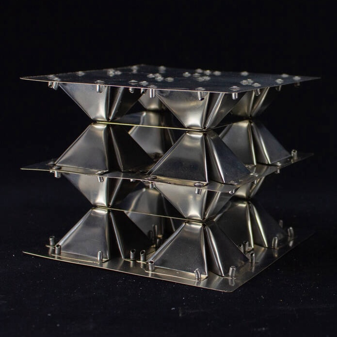
For this project, I plan to focus on creating a script that generates a 3D structure of plate lattices from an input outer mold surface and to prepare it for manufacturing. This task can be broken down into several segments:
- Learning to Interface with a CAD software like Rhino using python scripting
- Designing an algorithm to populate a target surface geometry
- Implement the algorithm into an actionable script
- Unraveling the CAD model into specific 2D surfaces with their generating crease lines
- Translate the 2D files into G-code for CNC milling.
Cell Design
One of the main issues for modeling this cell was the dynamics of the folded corner as the fold angle changes. I solved this using the intersection of circles, which insures that the corner's edges will always keep the same length.
I initially used grasshopper modules to generate the geometry, however, this would quickly become cluttered when moving on to arrays. To resolve this, I used a python module to write all of the operation as lines of code instead. Below is the graphical interface and the code for the basic parameteric cell.
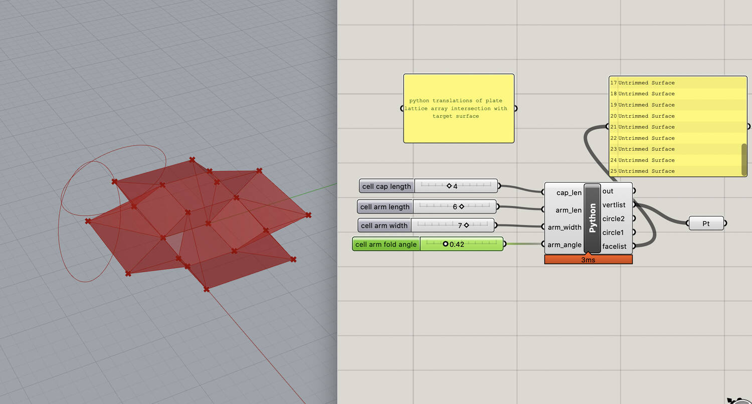
As you can see, I mainly started out by using functions, but I would later rewrite the entirity to be object oriented with a cell and array class. Finally, as a quick first attempt, I generated an array of cells and intersected it with a bounding surface, in this case, a sphere.
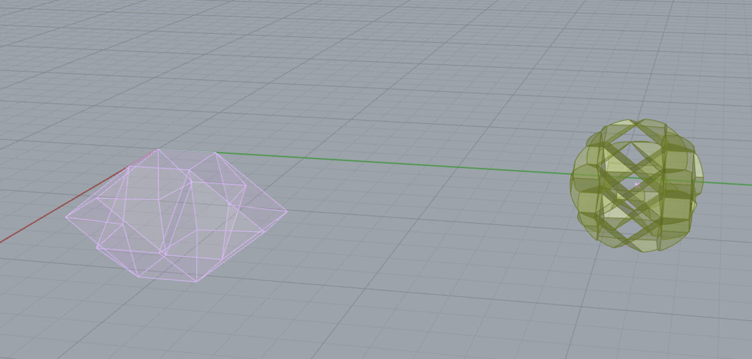
I originally thought that this was roughly what I needed to do, but it is actually much more complicated. Instead of simply cutting the cells,
I needed to detect the cells that intersected with the boundary surface, and then modify their geometry in a way that they would fit, essentially squishing in the parts that were out of bounds.
Developability as a major constraint (foldable from a flat surface).
Simple Cube Array
Before thinking about dynamic geometry that changes as a function of the boundary or integrated connector designs, I modeled a simple cube array that we could use for initial tests.
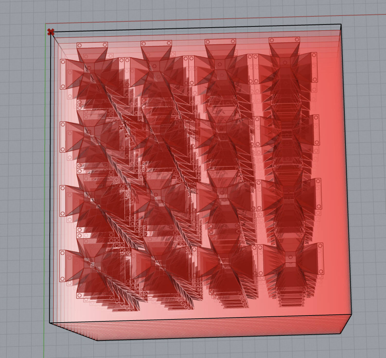
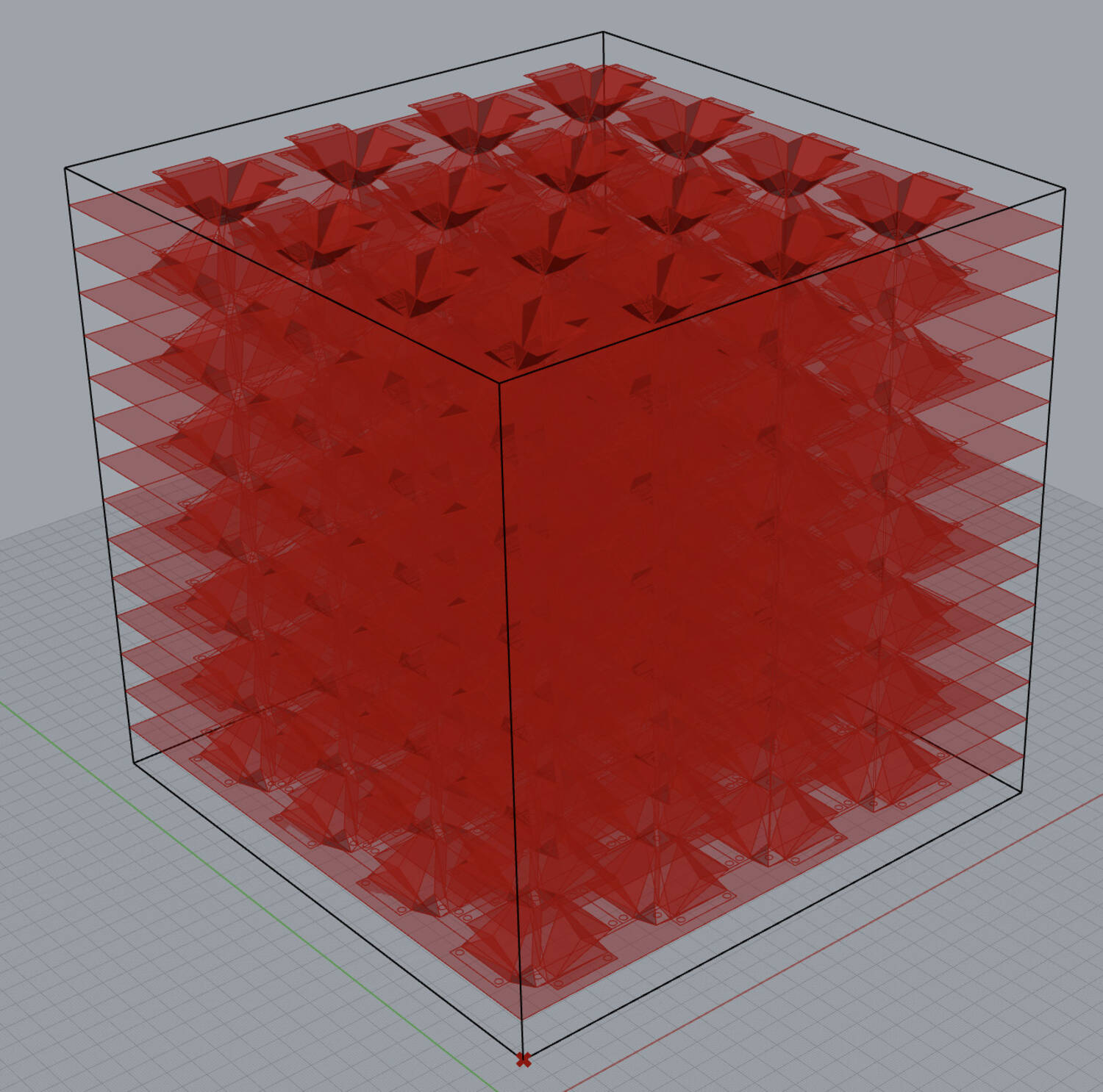
In this design, the cells are held together using plate support layers. The cells have rectangular flaps to support each face which are then fastened to the supporting plate layers.
Exporting to 2D
Further in development, I added a feature that unfolds all cells in the intersection array. I then assigned colors for different creases, mountain or valley. This distinction will allow us to seperate the lines to score on the top or the bottom of the sheet when prototyping with aluminum foam.
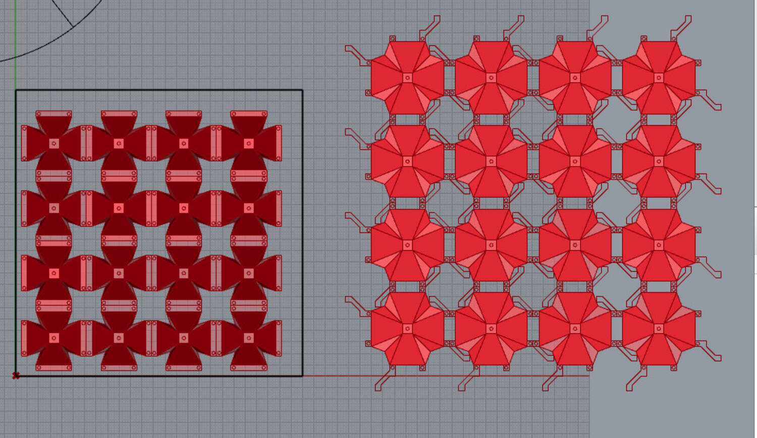
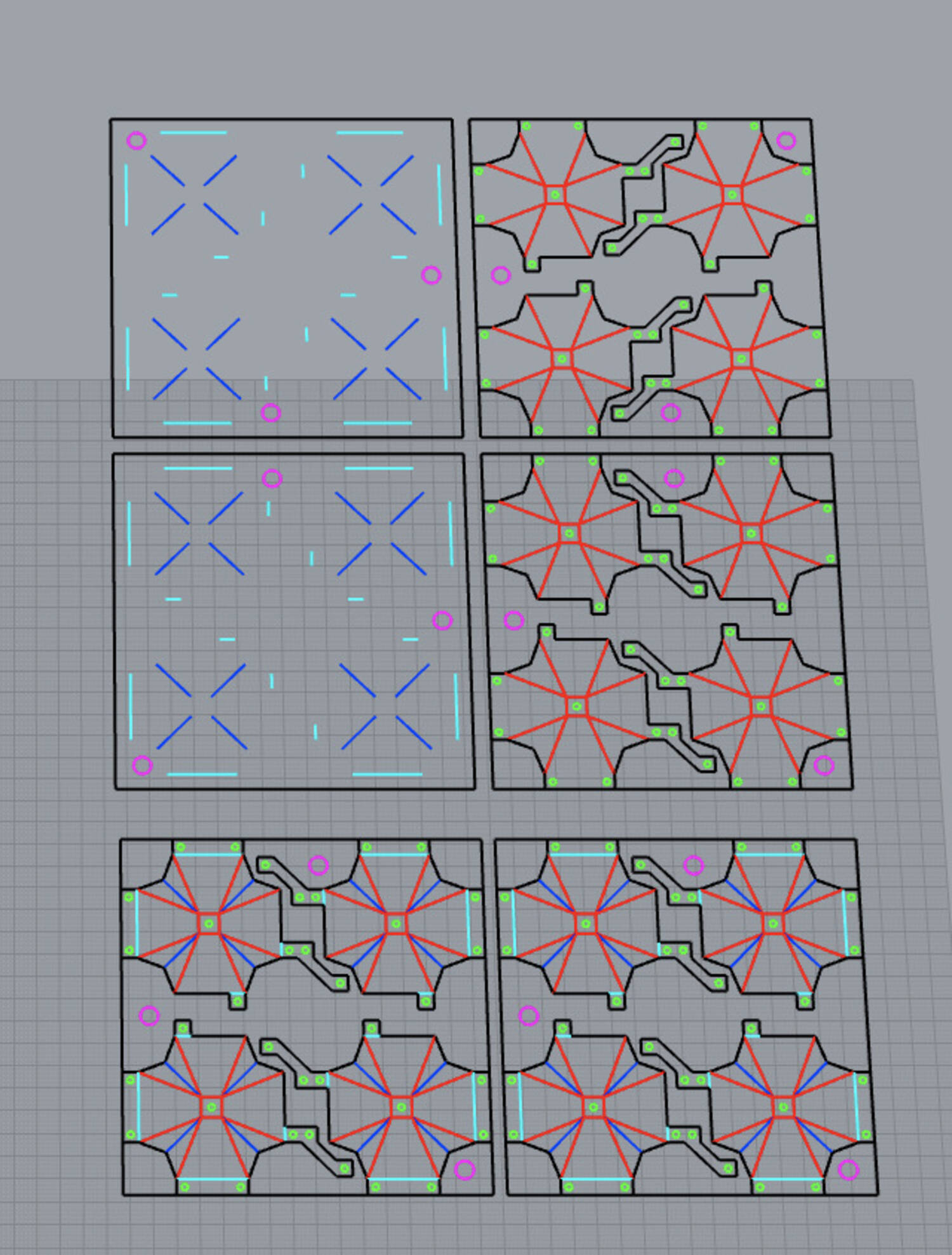
Here you can see the final lines that were exported for milling a cell prototype. This was later modified for laser cutting outlines out of stainless steel with stamping as opposed to milling creases and manually folding the cells into place.
Boundary Edge Cases
To address confomability, I broke down cases based on which vertices were excluded from the boundary. You can see the cases I considered in the sketches below.
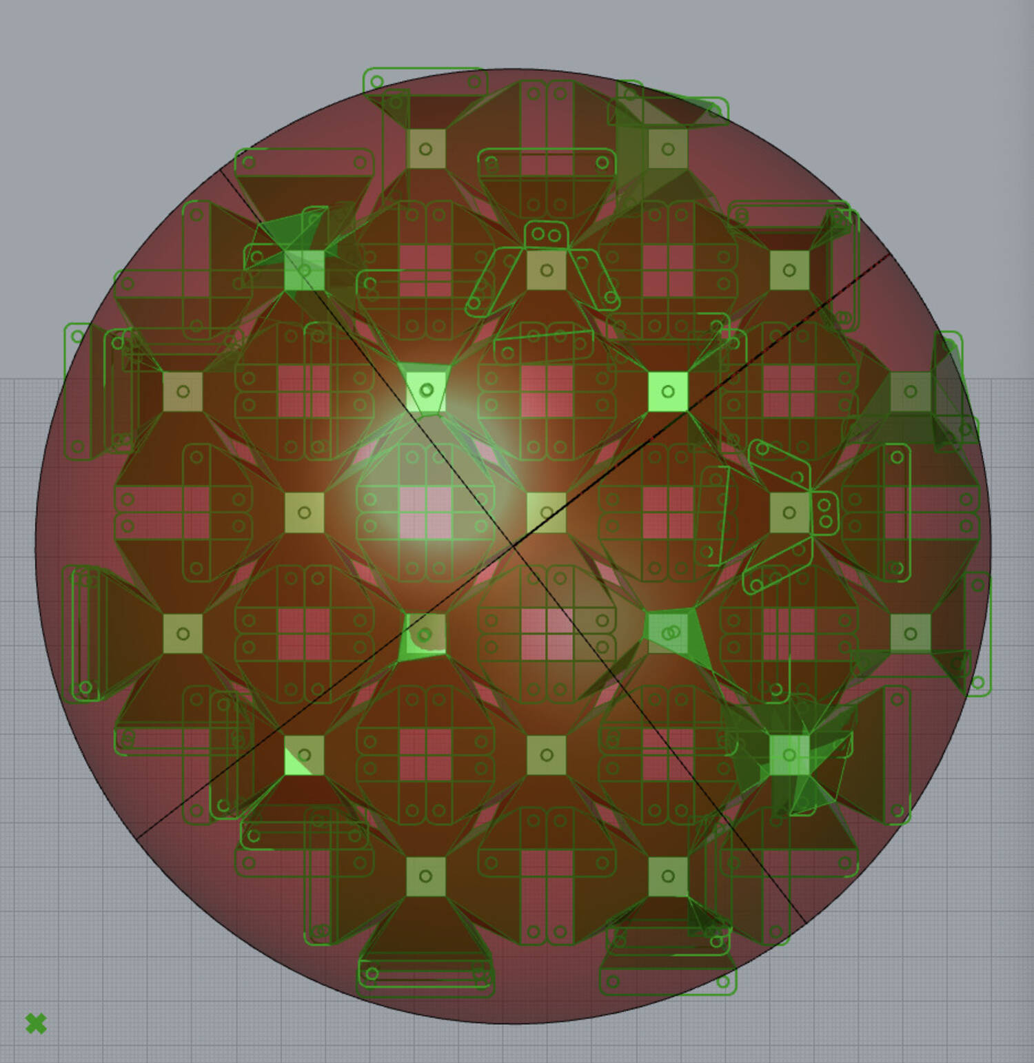
Originally, I had not considered developability when designing the solutions. I later developed a simple function to check that the angles around each vertex add up to 360 degrees or 2pi radians. The approach was simply to find the intersection points and use those as new vertices. If all four top verticies were out of bounds, then three were selected to define a plane, which then defined the fourth vertex. This approach was adapted to many cases where it was applicable. Since creating a program that generates cells and their outline for testing was the main priority, I did not explore the morphing alogrithms to completion. This is reflected in some of the images were there were some edge cases or bugs that deform boundary cells in weird ways.
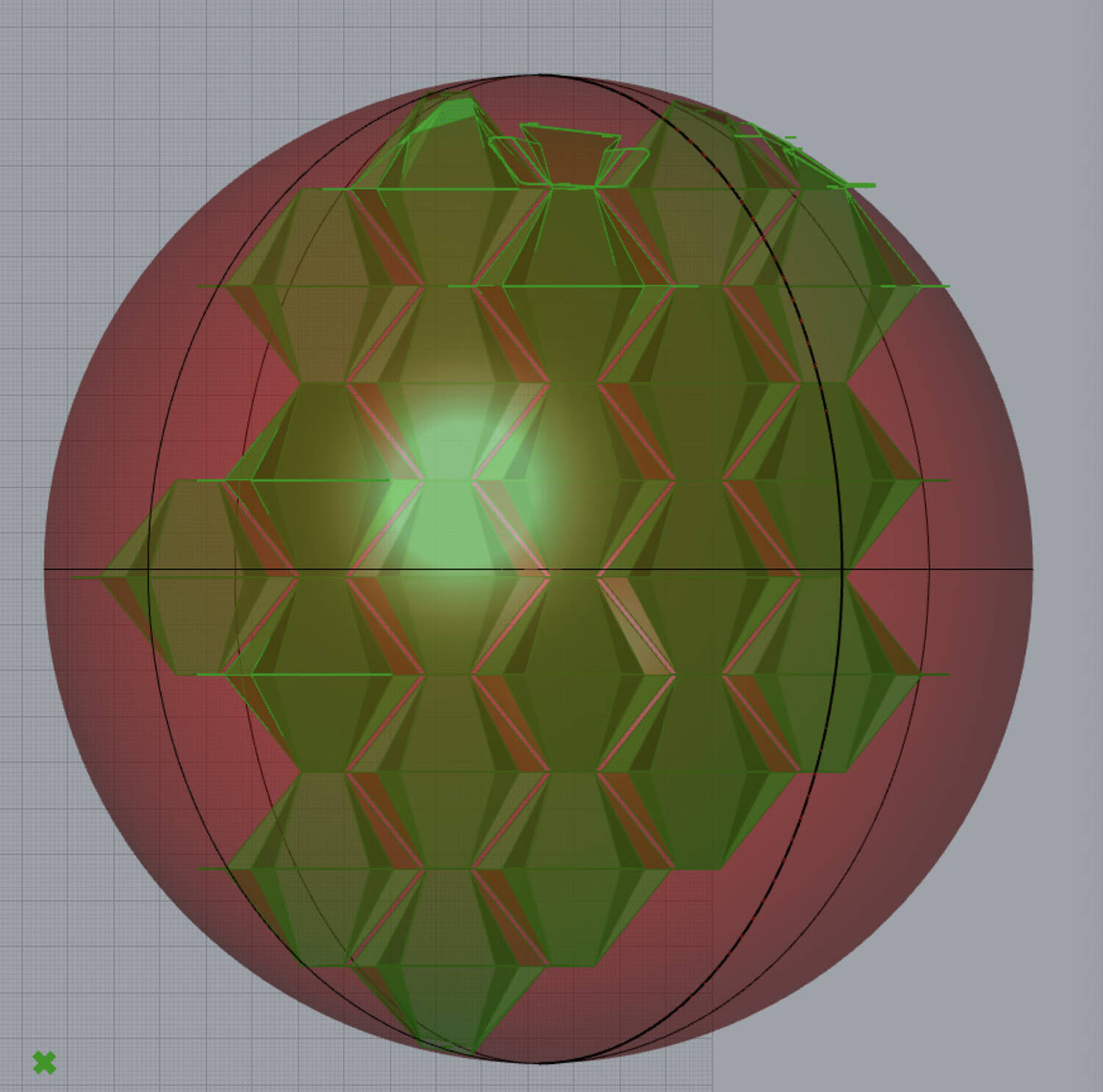
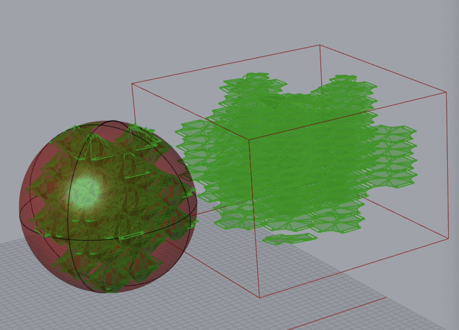
This illustrates the approach in action for a sphere boundary surface. Note that cells that satisfied cases that were not implemented were toggled off for visibility
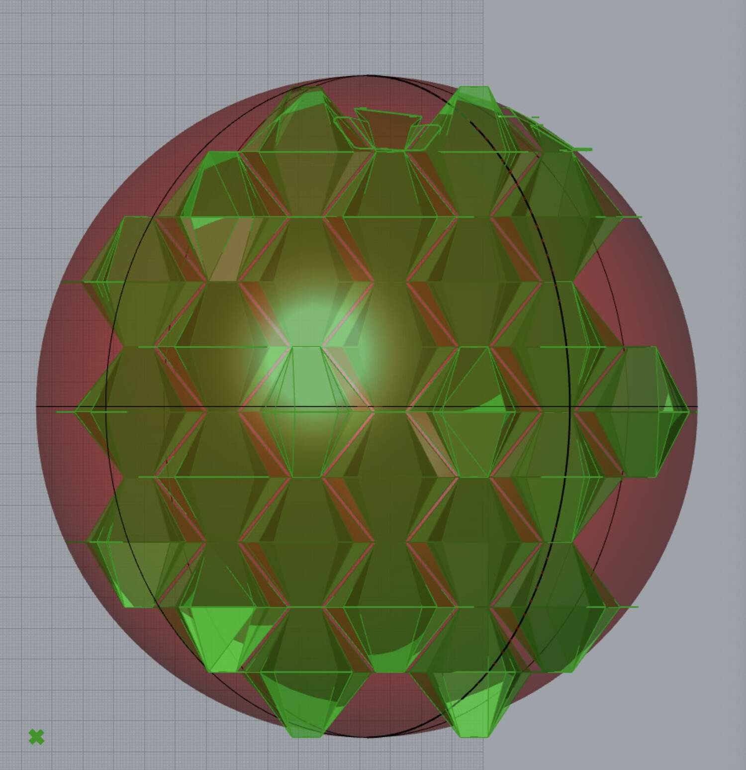
Here I attempted implementing the case for side intersection, which caused some self intersection issues or missing vertices.
Conclusion
In summary,
- I first learned the grasshopper interface and modeled the cell geomeotry using function blocks
- To model the cells parametrically, I solved the folding dynamics using circle intersections
- Next, I learned to interface with grasshopper using python for more control and compactness
- Then, I modeled a cube array with simple tab connectors and plate layers
- For prototyping, I unfolded the array cells and exported them as 2D files
- I then explored various extensions such as integrated connector design and morphing cell geometry
This project is continued in "Structural Origami II". I continue to refine the code for cell arrays to handle practical manipulations during the manufacturing phase of this project as well.With all the additional features and class methods, the final code is about 2000 lines.