Manufacturing of Folded Plate Lattice
This is the continuation of my work during the Spring where I worked on modeling the geometry in Rhino and Grasshopper.
This page summarizes my work as an undergraduate researcher through Summer 2023 for the Center for Bits and Atoms lab in the MIT Media Lab.
I worked on developing a manufacturing method for a novel plate-lattice geometry macro-meso metallic foam designed by my supervisor Alfonso Parra Rubio.
Read about his prior work on folded structures previously featured on the MIT frontpage
Project Statement
Objectives
This project can be broken down into three objectives:- Creating a parametric CAD representation of the cell array with variable fold angle and dimensions. Finding a solution to formulate irregular cells intersecting the surface
- Creating an appropriate manufacturing technique and cell design for integration
- Testing and iterating with different parameters to optimize the performance
Previously, I focused on the first objective: creating a script that generates a 3D structure of plate lattices from an input target surface and to prepare it for manufacturing.
As of now, I created a script that can generate an array that fits a bounding box of the target surface, and then trims all the cells to be contained inside the surface. Since I had to learn grasshopper functionalities as well as develop and debug an implementation method, this took a month of gradual development.
As the next step, I moved on to recreate the same process using a single Python module and Rhino API to interface with Rhino. The idea is to create code that is exportable, give me finer control of the Rhino objects as well as develop my understanding of the implementation. Over the course of a few weeks, I have recreated all the vertices of a single cell and the folding constraints by manipulating the vertex coordinates and thoughtful use of geometry. I have also managed to generate the cell surfaces and points in Rhino using Rhino geometry functions, then generate an array of these cells to populate the bounding box of the target surface.
I am now working on creating a test array of points that will sort which cells will be included or bound to the target surface. This will hopefully improve the time complexity when generating cells subsequently. Before the end of the Spring semester, I plan to complete the creation of irregular boundary cells and move on to the next component of the project.
For this summer UROP, I aim to work on the manufacturing and potentially the testing part of the project. This involves a few possible pieces:- Writing a script to extract the 2D geometry from the parametric CAD model
- Designing cells that can lock with each other instead of using large sheets of metal to connect each cell with many rivets
- Creating or modifying manufacturing techniques in order to produce an entire cell by stamping sheet metal or eventually some other method
Stamping
Stamping allows the use of material stronger than aluminum such as stainless steel, and is more suitable for larger scale rapid manufacturing.
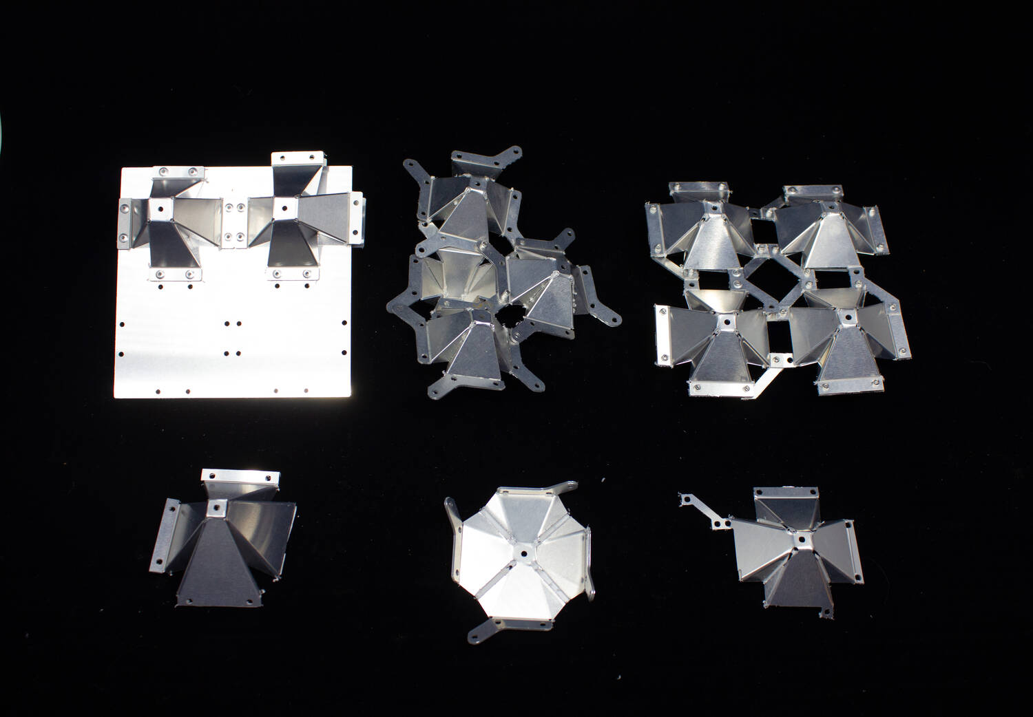
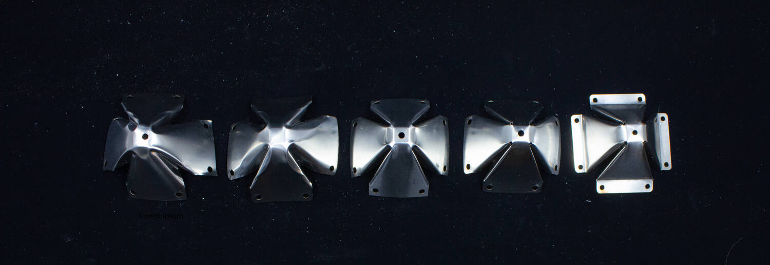
To accommodate the relatively complex vertex geometry of the cells, it is practical to use thinner sheets to avoid self intersection of the material and other smoothing behavior at the vertices. To mitigate these issues, a small hole is cut out of each vertex.
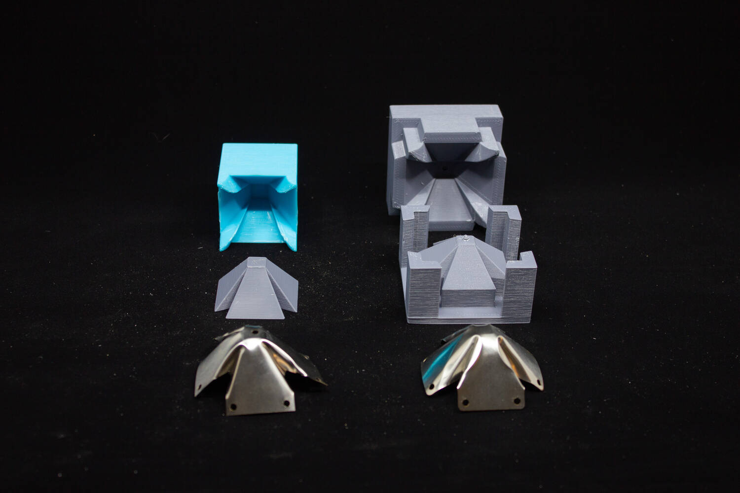
We observed that the sheet metal was not adequately constrained to the mold shape when stamping to the final geometry in a single step. The steep angle of the mold allowed the material to wander into different configurations (such as a saddle shape) that would prevent the forming of the desired geometry. Attempts to smooth out the mold or create a deeper mold with ramps to guide the faces of the material also failed. This is why we chose a progressive stamping process.
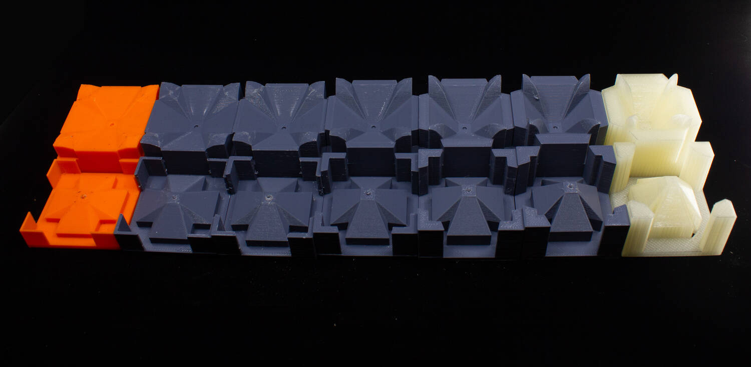
By using an additional step with a shallow mold to lightly crease the material, the creases that are formed help guide the folding process in later steps. A second in-between step helps to accentuate the creases and constrain all the faces to fold simultaneously before the final forming step.
Assembly Process
There were several things to consider when exploring the assembly process
- Fastening: rivets and welding
- Connectors: support plates or integrated
- Configuration: cube array or body centered cubic (additonal cell in the middle)
The idea is that rivet assembly or a cube array with support plates is the most sure way to assemble everything. However, the alternative options each have something to potentially offer in terms of manufacturability or performance.

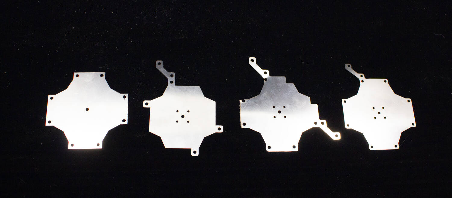
Using integrated tabs could make the support plate unnecessary, which would reduce the weight and improve the scalability of the overall design.
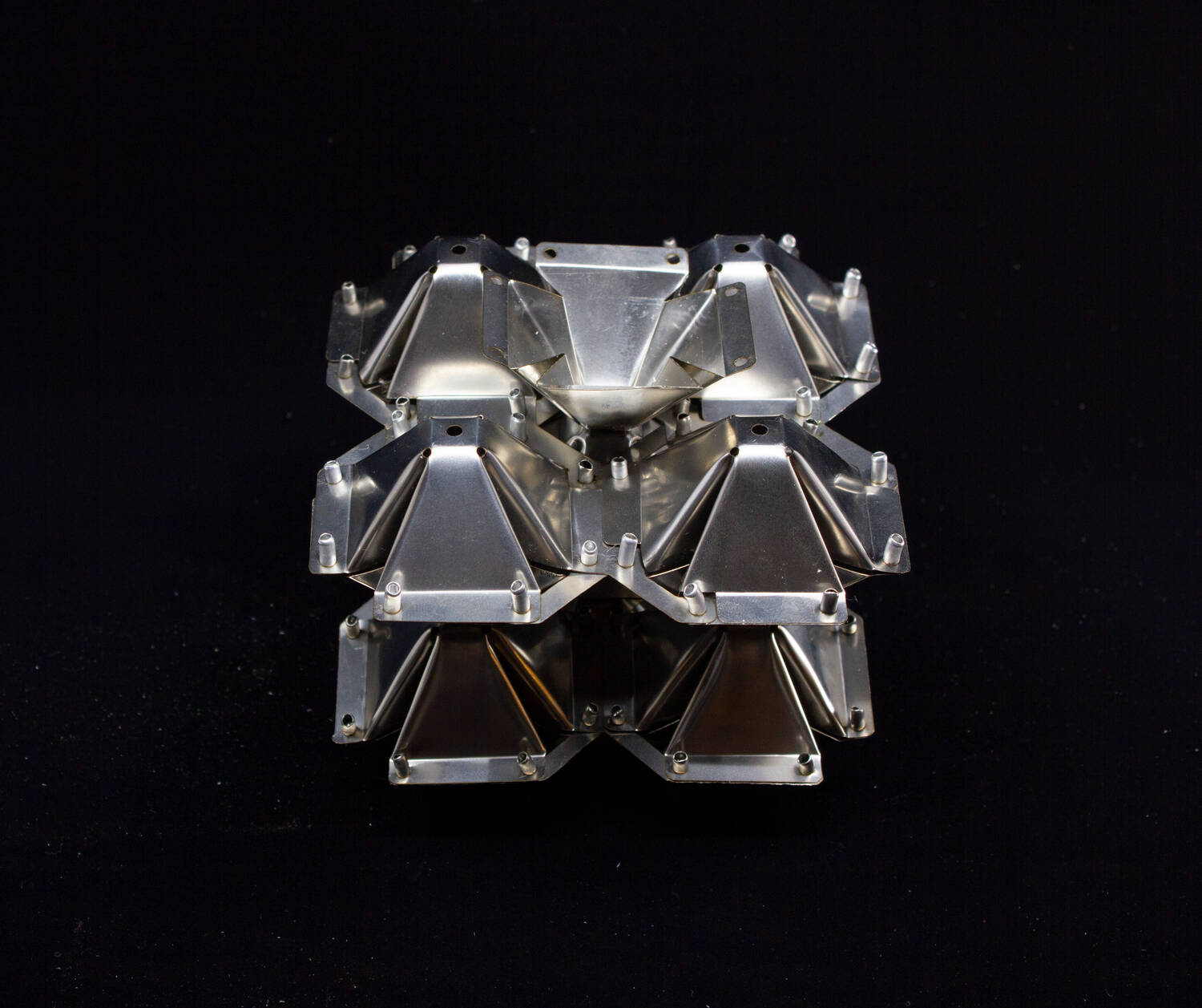
While assembly without support plates was indeed possible, the structure was much more flexible and more difficult to assemble.
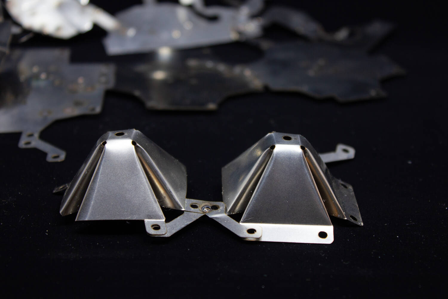
Welding could allow easier modeling, better performance and potential for automation.
Results
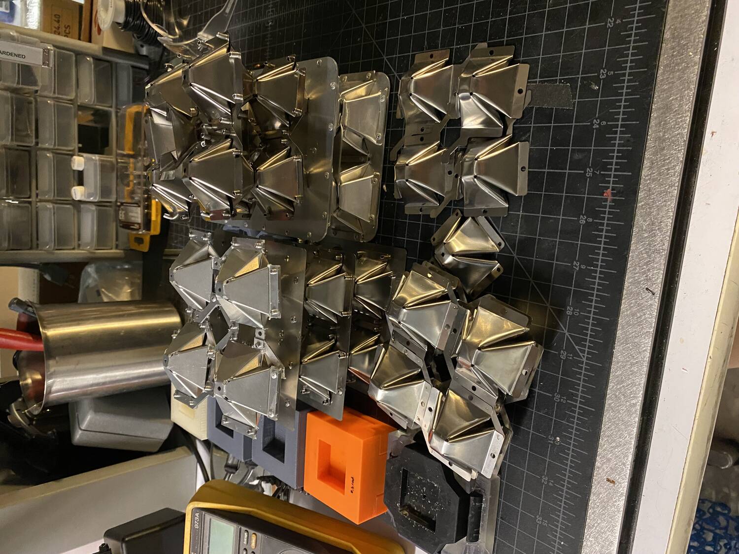
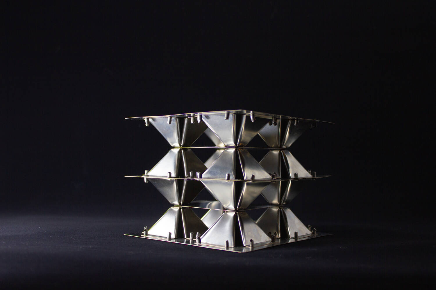
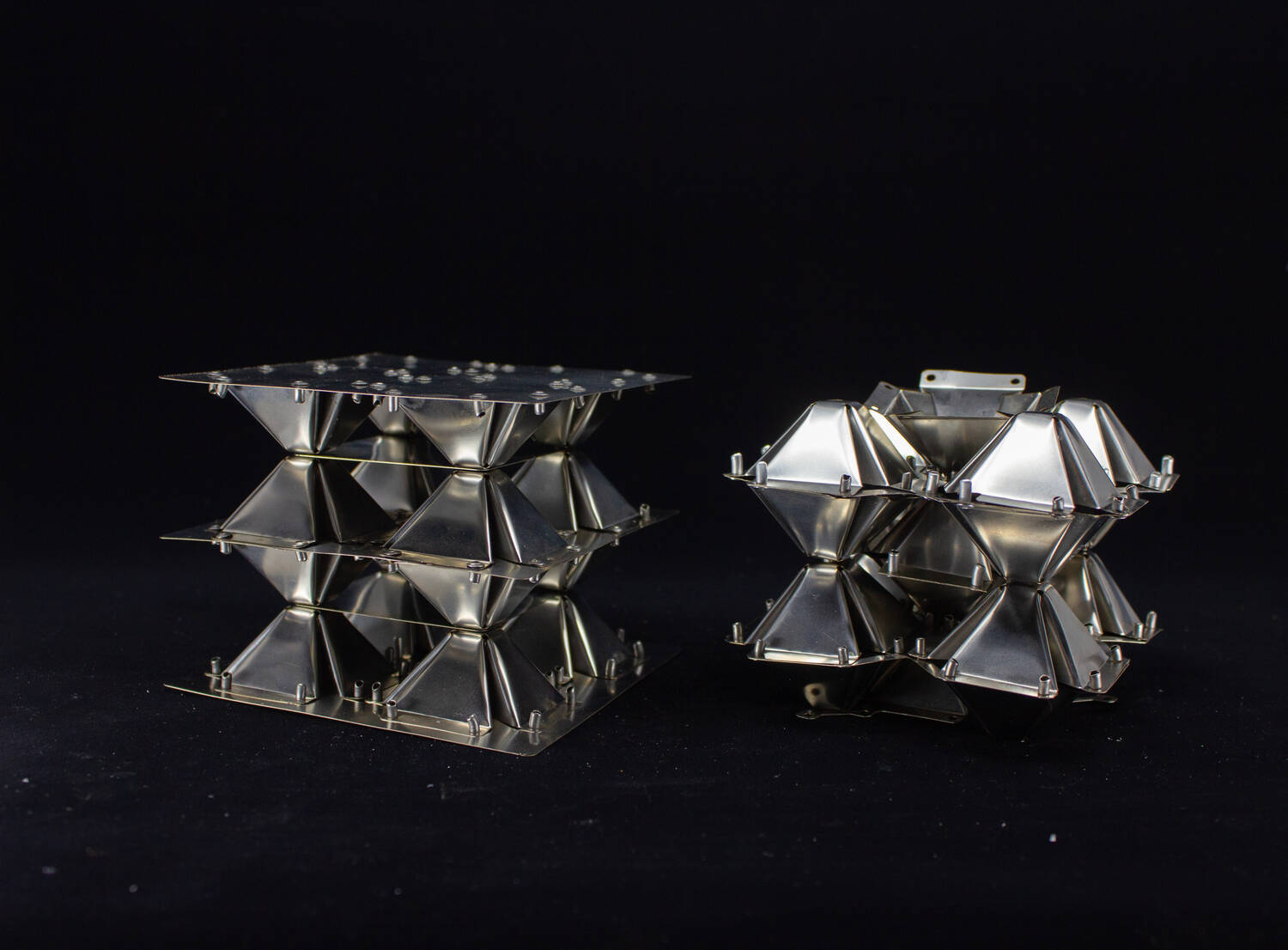
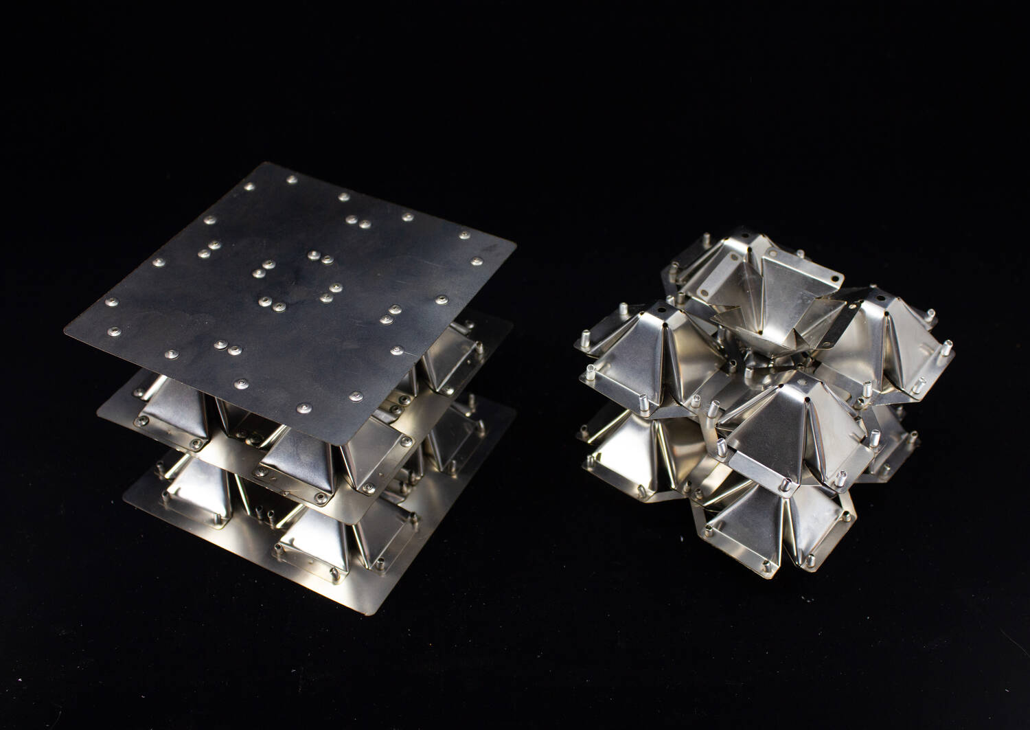
As the final deliverables for the summer, we ended with one assembled cube array with rivets and support plates, as well as one bcc array with integrated connectors. Additionally, single layered square arrays were made for further development.
Conclusion
In summary,
- Progressive stamping was selected after initial tests and molds were designed parametrically
- Alignment and folding features were added to get a crisp and accurate cell
- Different fastening methods were explored, rivets and pulse arc welding
- Different attachement features were explored, support plate or integrated tabs
- Two geometries were implemented, simple cubic and body centered cubic
