Drawbar Transducer
This page presents a summary of my work designing a drawbar transducer as an intern at the John Deere Product Engineering Center in the summer of 2024.
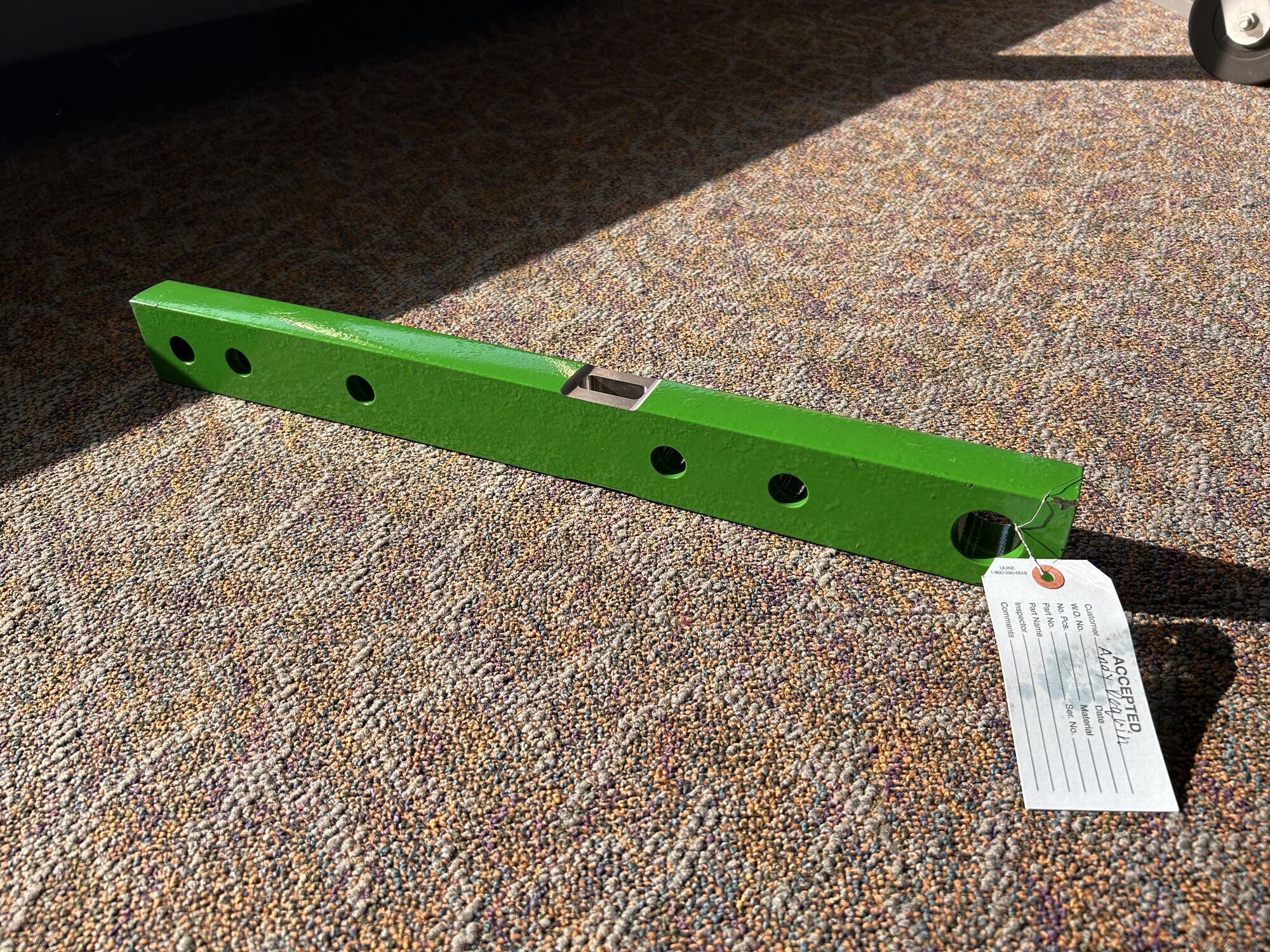
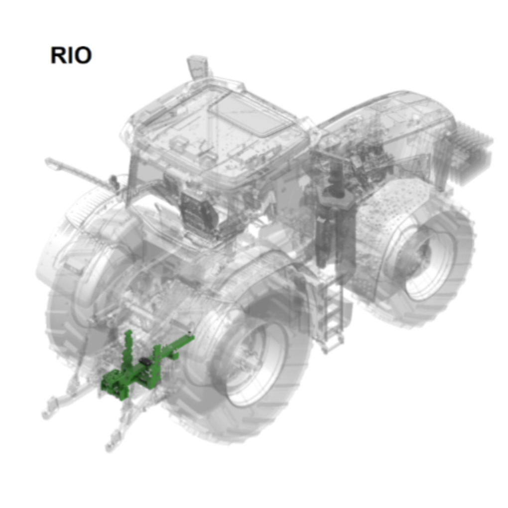
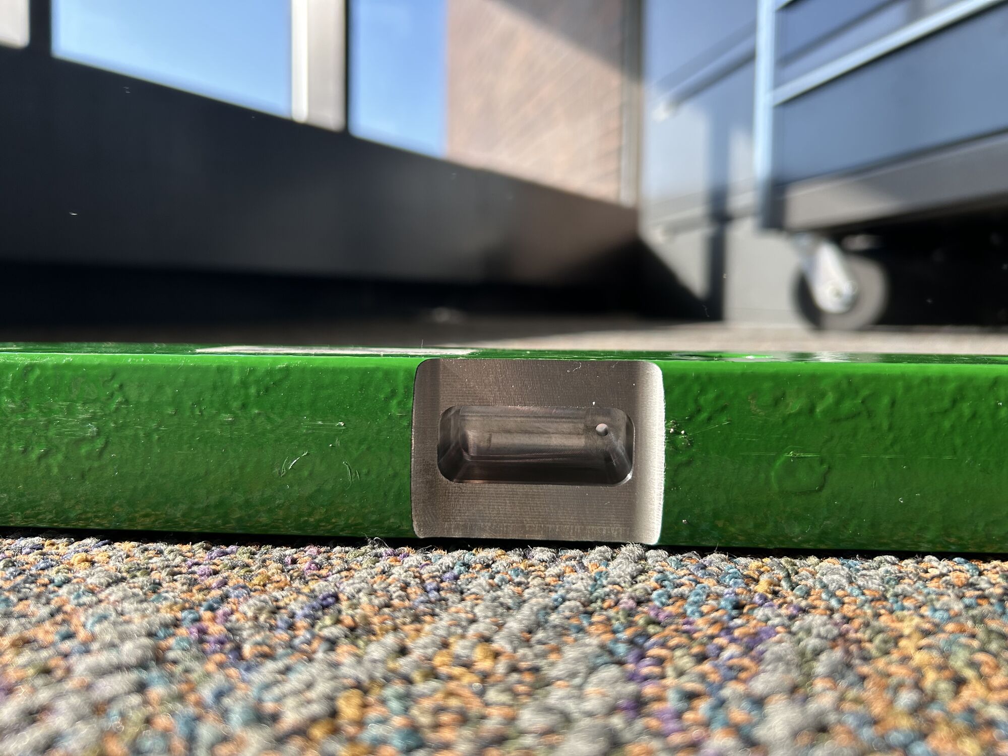
What is a drawbar? The drawbar is a bar on the tractor, or any vehicle to which things like farming tools can be attached to and pulled. A transducer converts a mechanical signal like strain into an electrical signal. The drawbar modified into a transducer through the use of strain gauges. In this case, designing a drawbar transducer entails modifying the drawbar geometry for optimal sensitivity to strain while staying below the stress limit. Since drawbars are the connection point between the vehicle and the pulling load, it can provide useful information in the case of failures or the state of the tractor in general.

Project Overview
Unfortunately, I don't have much media to present as much of it is confidential, but I can outline the general process.
- Gathering information: task details, loading conditions, harshness of conditions, material properties, relevant contacts and processes, etc.
- Modeling Excel Spreadsheet: modeling bending, shear, and axial stress and wheatstone bridge sensitivity
- Designing Geometry: learning CREO and modifying the drawbar geometry according to stress and strain models
- FEA Analysis: coordinating with the simulation department for more accurate stress and sensitivity results
- Mentor Feedback: ask for mentor feedback to confirm design
- Iterate: consider multiple strain-bridge placements and cross-section geometries
- Work Order: submit a work order with technical drawing and coordinate with technicians

Next Steps
Due to many weeks of significant project contacts being out of office and four weeks of lead time, the drawbar was only machined at the end of my internship time. However, the next step would involve coordinating with technicians for the following parts.
- Attaching strain gauges: applying at the specified locations on the modified geometry
- Wiring:connecting the shear bridge, bending bridge, and axial bridge to a data acquisition system
- Protection:covering the components with silicon epoxy or additonal caseing if necessary
- Shipping:following international shipping regulations for packaging