Telemetry System
This page summarizes my work designing a telemetry system as a John Deere product engineering intern in the summer of 2024.
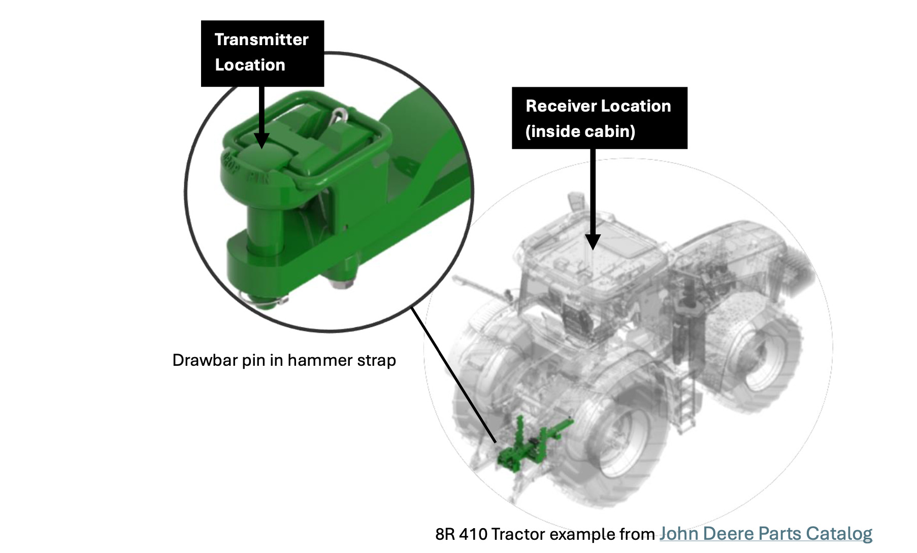
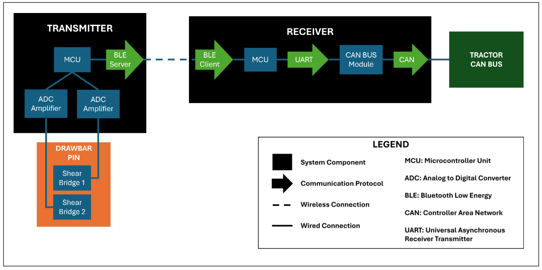
A telemetry generally allows data collection of data in hard to reach or rotating sources. This custom telemetry system was constrained to fit on the 2x2 inch area of a drawbar pin and needed to cost significantly less than the current $10,000 solution. As the only person on the team working on this project, over the course of a few weeks, I did the component selection, system design, hardware integration, wrote the firmware, fixed the libraries, designed the housing, wrote 70+ pages of documentation, and validated the device by testing it on a tractor. The system used ESP32C3 for Bluetooth communication between receiver and transmitter, two HX711 amplifiers, and a Serial-CAN module to connect to the tractor’s CAN bus.
My solution not only fit on the pin, but also was a 100x cost reduction from the current method. With a 10-week timeline, even with a four-week setback due to issues with ordering components and juggling multiple projects, I was able to make the system, test it, and write thorough documentation.

System Design

Components


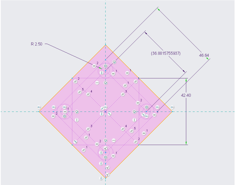
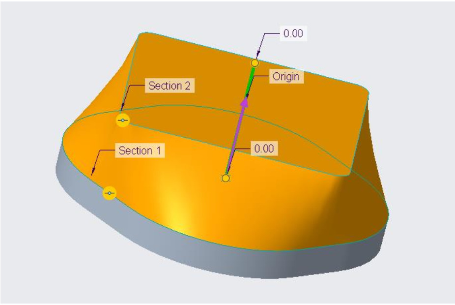
Housing Design

